usage: fastshft
fastshft is an MSDOS program that delivers a configurable sequence of visual stimuli at the left and right margins of the upper hemifield of a video display. It sends an event code at the beginning of each stimulus, at each horizontal shift of the joystick (or other game port input device), and at the beginning and the end of each block of stimuli. (A previous version of fastshft was implemented in Microsoft QuickC, sent event codes via the parallel port only, and handled processor interrupts. This document discusses only the current version, which is implemented in 80286 assembly language can be configured at compile time to send codes via a serial port or a parallel port, and ignores interrupts.)
| STIMULI |
The program begins by reading unsigned byte (range 0 through 255) stimulus codes from the file STIMULI.DAT in the current directory. No bounds-checking is performed as the contents of the data file are stored; thus it is possible for a large data file to overwrite fastshft's executable code. If this happens, unpredictable behaviour will ensue and you'll need to reboot the system. The absolute limit on the number of entries in the data file is 65280 (hex FF00) minus the size of the executable file FASTSHFT.COM. This quantity generally will not exceed 63800.
Configurable aspects of stimulus display are associated with stimulus codes read from the configuration file STIMULI.DAT, and events to be logged by the data recorder are associated with event codes sent through the serial port. Some occurrences, such as target stimuli and trial control, have both stimulus codes and event codes:
| EVENT | STIMULUS CODE | EVENT CODE |
|---|---|---|
| left background stimulus | 1 | |
| left target stimulus | 2 | 2 |
| right background stimulus | 3 | |
| right target stimulus | 4 | 4 |
| begin trial attending left | 5 | 5 |
| begin trial attending right | 6 | 6 |
| end trial | 7 | 7 |
| left response | 126 | |
| right response | 127 | |
| start recorder | 132 | |
| stop recorder | 136 |
The target and background codes cause the respective stimuli to appear at the left or right edge of the screen. Drawing and blanking of these stimuli are synchronised to the video hardware's vertical sync pulse in order to avoid flicker and to ensure constant, reliable display timing. Each display cycle consists of four sync periods. At the usual vertical sync timing of 72s-1, a single sync period is 13.89ms and thus a display cycle is 55.56ms. If stimuli are alternated between the two different sides of the display, as is the usual procedure in the two-location steady-state paradigm, the resulting stimulus period is 111.11ms and thus the stimulus rate is 9s-1 with a 50% duty cycle, with the two locations exactly out of phase.
| EVENTS |
During its initialisation, fastshft examines BIOS memory (segment 0040h) to determine the host machine's I/O configuration and port addresses. It is assumed that the machine contains at least one parallel port and at least one serial port. If the machine contains more than one serial port, the first expansion serial port (COM2) is used; otherwise the program defaults to COM1. The serial port is set for eight data bits, no parity, and one stop bit (8N1) at a baud rate of 19200.
Target codes (code 2 and code 4), in addition to causing a target stimulus to be displayed, are copied onto the serial output line so that target events can be logged by a recorder. Responses are also logged: fastshft polls the game port input at the beginning of every refresh cycle, and places an event code on the serial output if the game port's status has changed since the last poll.
| TRIAL CONTROL |
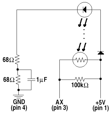
The two `begin trial' codes cause the software to display a white square in the stimulus location on the designated attended side, and then to wait for a key to be pressed. If that key is a control-C, the program aborts. Otherwise, the program waits until the state of the input device matches the designated side. The program then sounds a tone to signal that the scan should begin, and monitors the parallel port's BUSY input for a negative-going sync pulse from the scanner (see the `hardware' section of this document for information on coupling the scanner pulse into the parallel port). When a sync pulse is received, or when an override has been received from the keybord, the recorder start code (132) is then output via the serial port, and the white square is removed. (132 is the start code accepted by the ISCAN data recording system when serial triggering is enabled; see the ISCAN documentation for details.) After waiting for a period of at least one and no more than two vertical sync cycles (at least 13.89ms and no more than 27.78ms) so as to give the data recorder time to start, fastshft sends a strobe pulse (negative-going, ~5µs duration) on the parallel port to trigger the MRI scanner, and then presents stimuli until an `end trial' code (code 7) is reached.
On encountering an `end trial' code, fastshft sends the `end trial' code via the serial port, waits for a period of one to two vertical sync cycles, and then sends the recorder stop code (136).
| EYE MOVEMENT CALIBRATION |
| TERMINATION |
| HARDWARE |

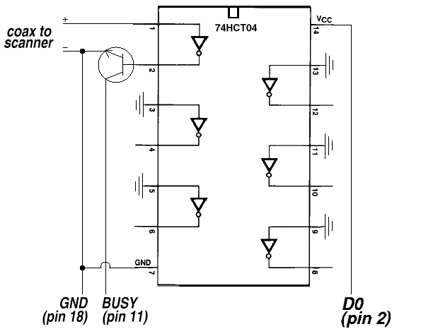
The General Electric Signa scanner can be configured to provide a negative-going TTL sync pulse at the start of scan or at the start of each excitation. We use a 7404 inverter to buffer this signal into a transistor which pulls the parallel port's BUSY input down to ground during the sync pulse. Power for the inverter is drawn from the data line D0. On older parallel ports, this data line may not be able to provide more than 3V and may not be able to source much current; hence, for maximum compatibility, our design uses the 74HCT04 CMOS version of the chip:

Author: Matthew Belmonte.